Electric: Substation
A substation can best be thought of as a giant set of transformers (Figure 19). Substations in cities (Figure 20) are part of a network of other substations permitting electricity to be rerouted when necessary.
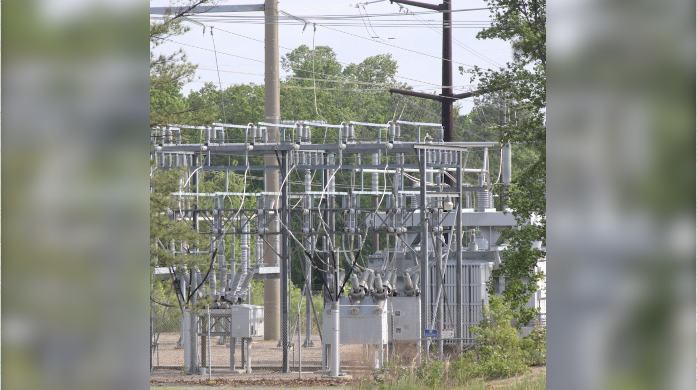
Figure 19
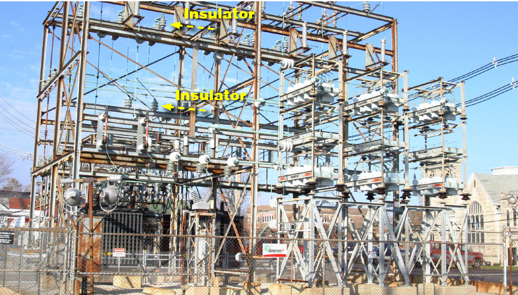
Figure 20: Insulators support high voltage wires and prevent electrical current from leaking to ground or other conductive materials inside the substation. Insulators can be made of glass, porcelain, plastic or silicone.
Low voltage circuits are used within substations to power metering equipment (Figure 21). High voltage bushings use insulating properties to protect metal equipment. A surge arrester (Figure 22) diverts lightning and limits the voltage.
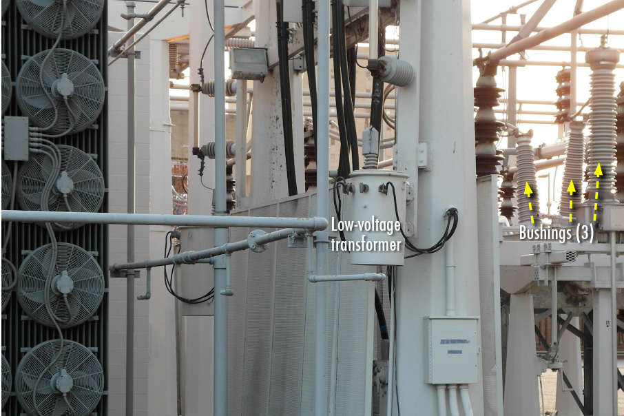
Figure 21
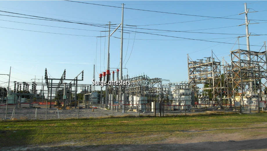
Figure 22
69kV is what’s known as a sub-transmission voltage in many electric distribution systems, although in some systems 69kV is considered a transmission voltage (Figure 23).
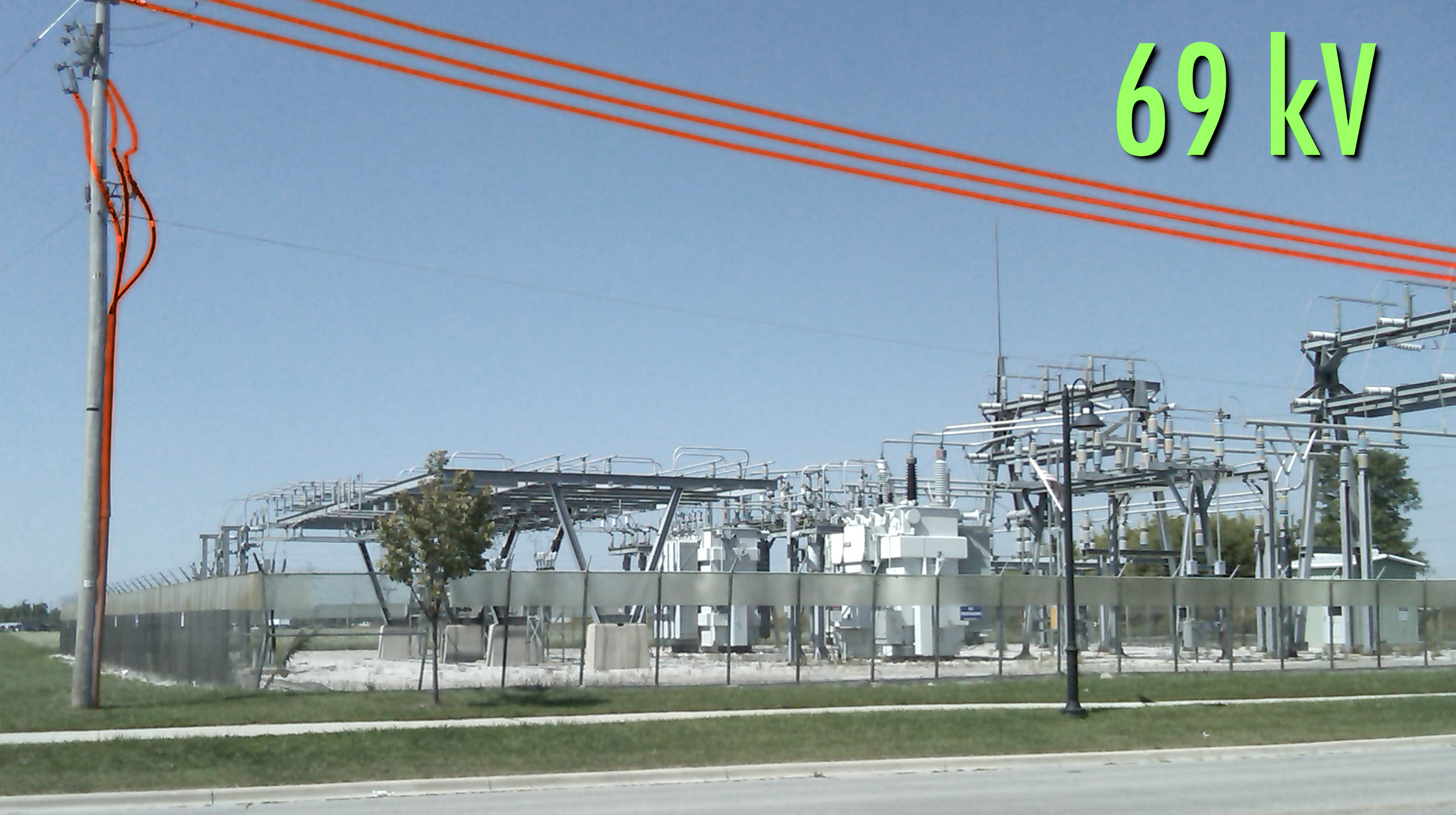
Figure 23
Here are the basic parts of a substation (Figure 24).
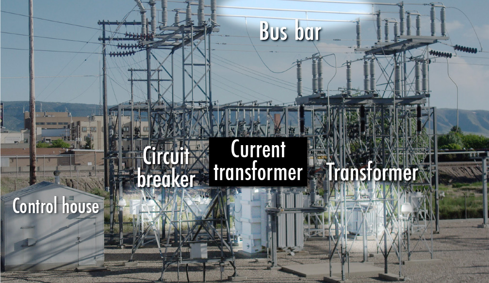
Figure 24
Bus bars are conductors that connect the aerial lines coming into the substation with the equipment inside the substation. Oil-filled circuit breakers protect the substation in case of an electrical overload. Transformers reduce the voltage, and voltage regulators ensure that the right amount of voltage leaves the substation (Figure 25).
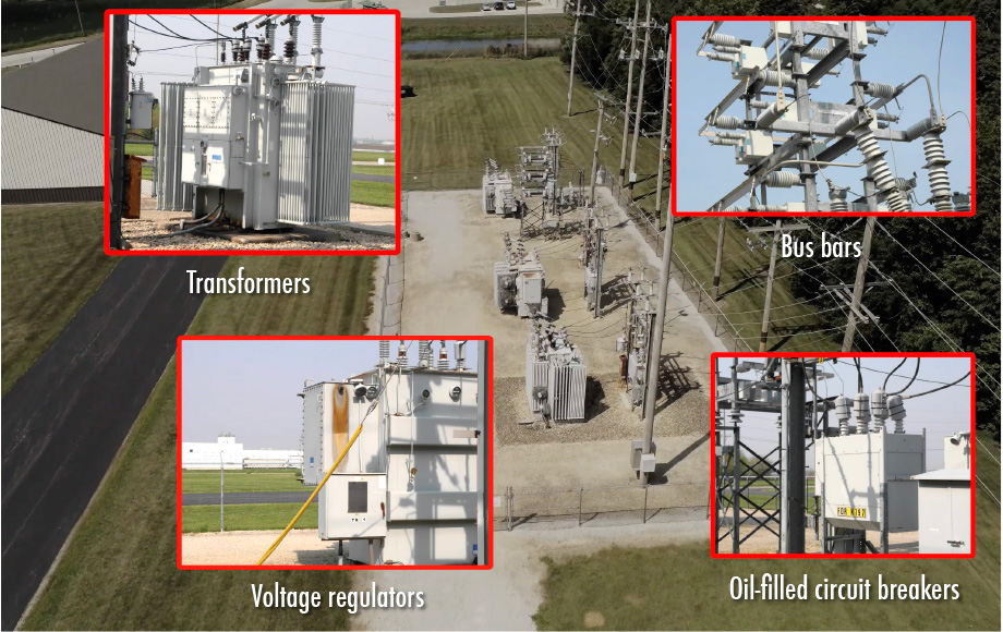
Figure 25
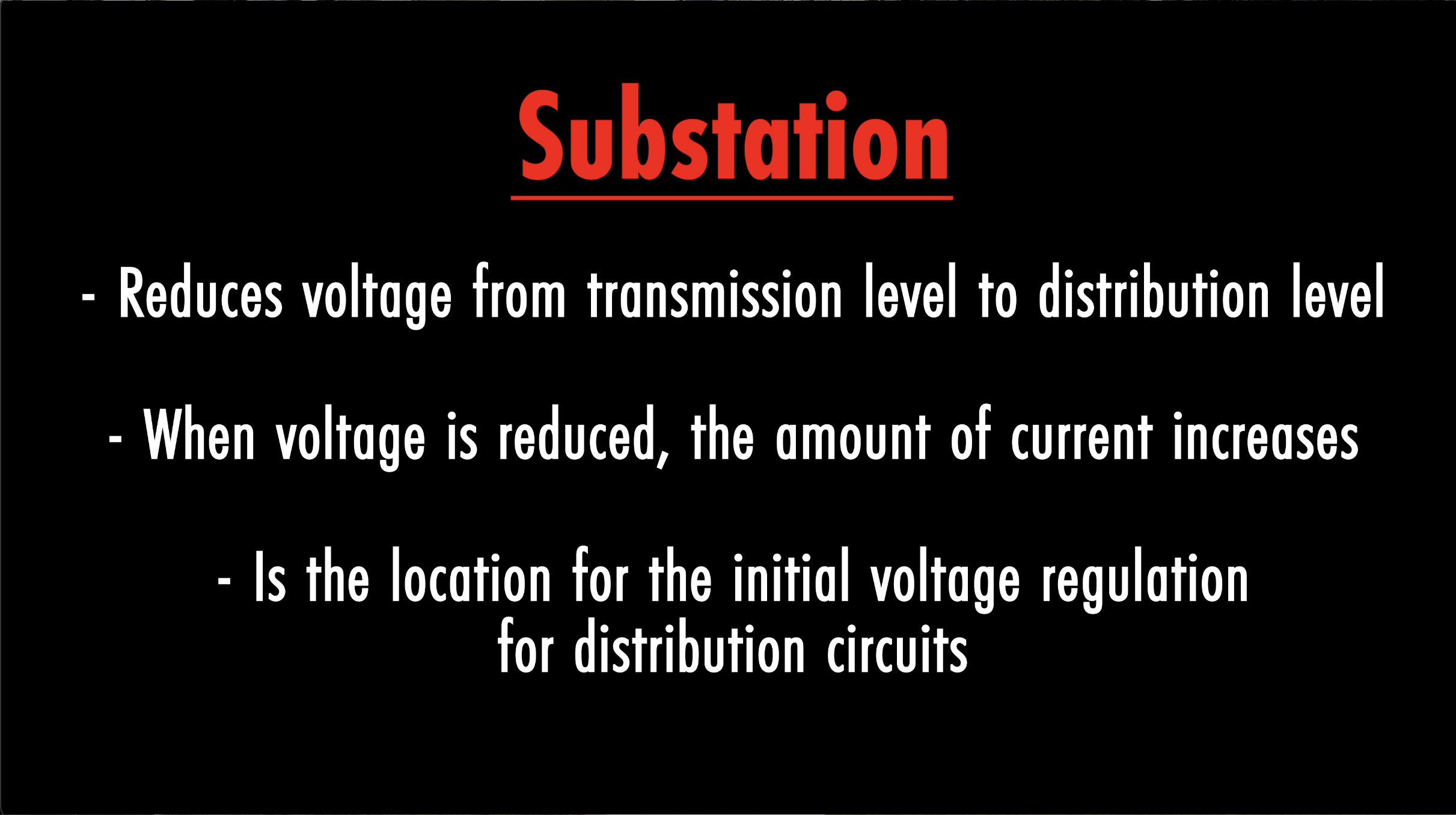
Figure 26